
Trilayer PVDF nanocomposites with significantly enhanced energy density and energy efficiency using 0.55Bi0.5Na0.5TiO3-0.45(Sr0.7Bi0.2)TiO3 nanofibers
 0
0
Abstract
The development of dielectric capacitors with high energy density and energy efficiency is of great significance in the modern electronic components market. To reduce the high energy loss of Bi0.5Na0.5TiO3, 0.55Bi0.5Na0.5TiO3-0.45(Sr0.7Bi0.2)TiO3 (BNT-BST) nanofibers with a high aspect ratio are synthesized via electrospinning. To achieve a high energy density, the design of a symmetric trilayer nanocomposite consisting of a BNT-BST/polyvinylidene difluoride (PVDF) layer with a high dielectric constant sandwiched between two layers of pure PVDF is herein described. The trilayer structure can effectively alleviate the electric field concentration effect, resulting in a considerably enhanced breakdown strength and improved discharge energy density. The maximum discharge energy density of 17.37 J/cm3 at 580 kV/mm could be achieved in the symmetric trilayer nanocomposite with a BNT-BST/PVDF middle layer, which is 90.5% greater than that achieved using pure PVDF
Keywords
INTRODUCTION
The increasing global energy consumption and rising demand for low-carbon technologies in modern society have stimulated the development of renewable energy technology. Compared with electrochemical capacitors and batteries, dielectric capacitors have a higher power density and longer service life and are better suited for high-voltage, low-cost, and multifield applications[1-4]. Dielectric capacitors are therefore considered to be potential energy storage devices. Faced with the increased demand for the micro-nano integration of electronic components in modern society, it is technically challenging to simultaneously achieve high energy density and efficiency in dielectric capacitors[5-7].
Nanocomposite films, which integrate a ceramic filler with a high dielectric constant and a polymer matrix with a high breakdown electric field, provide novel ways for designing dielectric capacitors with high energy density[8-11]. The researchers improved the energy storage performance of nanocomposites by incorporating zero-dimensional (0D) ceramic nanoparticles, one-dimensional (1D) ceramic nanofibers, or two-dimensional (2D) ceramic nanosheet fillers into the polymer matrix[12-15]. Compared with 2D ceramic nanosheet fillers, 1D ceramic nanofibers are easier to synthesize. Compared with 0D ceramic nanoparticle fillers, the incorporation of 1D ceramic nanofibers with a high aspect ratio into a polymer matrix can considerably improve the energy storage performance of nanocomposites. Conversely, 1D ceramic nanofibers possess a greater dipole moment, which contributes to an increase in the dielectric constant. In contrast, 1D ceramic nanofibers have a smaller specific surface area and can be dispersed more uniformly in a polymer matrix, which is advantageous for alleviating electric field concentration and enhancing breakdown strength. Moreover, 1D ceramic nanofibers as fillers have a lower percolation threshold. This implies that the dielectric constant of nanocomposites will achieve its maximum value with a small amount of loading[16,17], as demonstrated by the work of Song et al.[18].
Bi0.5Na0.5TiO3 (BNT) ceramic is widely used in energy storage devices owing to its high dielectric constant and powerful saturation polarization value. However, pure BNT ceramics have a rhombohedral R3c structure and high remanent polarization value at room temperature, which would significantly impede the enhancement of energy storage density and energy efficiency of BNT ceramic[19-21]. A new binary system ceramic material could be created by combining relaxor ferroelectric Sr0.7Bi0.2TiO3 (BST) with ferroelectric BNT with extremely low remanent polarization values while maintaining the high polarization value of BNT at room temperature. For example, 0.55Bi0.5Na0.5TiO3-0.45(Sr0.7Bi0.2)TiO3 (BNT-BST) has a high saturation polarization value and low remanent polarization value, which is advantageous for improving the discharge energy density and energy efficiency of nanocomposites[22-24].
With the advantages of simple equipment, various spinnable raw materials, excellent fiber structure tunability, and strong expansion of preparation technology, electrospinning is an efficient and low-cost method for preparing nanofibers that have been rapidly developed in recent years and are widely used to produce organic, inorganic, and organic/inorganic composite nanofiber materials[25]. Polymer dielectrics with optimized multilayer structures have emerged to resolve the contradictions between nanocomposites with a high dielectric constant and high breakdown electric field. The multilayer structures use the blocking effect of the ordered interface on charge migration, which can effectively suppress the distortion of the local electric field and propagation of electrical tree branches and significantly elevate the energy storage performance of the nanocomposites[26-28], as demonstrated in our previous work[29].
In this study, BNT-BST nanofibers with a high aspect ratio and an average diameter of 280.8 nm were fabricated via electrospinning. Monolayer and symmetric trilayer polyvinylidene difluoride (PVDF)-based nanocomposites with varied BNT-BST nanofiber loadings were prepared using the solution-casting method. Further, 0-x-0 (where x is the weight fraction of BNT-BST in the middle layer) was designed and fabricated to evaluate the breakdown strength and energy storage behavior of PVDF-based nanocomposites. The breakdown electric field increases from 450 kV/mm for pure PVDF to 580 kV/mm for the symmetric trilayer 0-2-0 sample, and the discharge energy density increases from 9.12 J/cm3 to 17.37 J/cm3, which is 90.5% greater than that of pure PVDF. These findings may offer a general strategy for improving the energy storage performance of dielectric capacitors for high energy/power density storage systems.
MATERIALS AND METHODS
Materials. Solutions of CH3COOH, CH3OCH2CH2OH, 2,4-pentanedione C5H8O2, Ti(CH3(CH2)3O)4, and N,N-dimethylformamide (DMF, 99.5%) were purchased from Sinopharm Chemical Reagent Co. Polyvinylpyrrolidone (Mw = 1,300,000, Macklin), Bi(COOCH3)3 (99.9%, Macklin), NaCOOCH3·3H2O (AR, Aladdin), Sr(COOCH3)2·1/2H2O (AR, Aladdin), and PVDF (6020, Solvay) were used.
Synthesis of 50 mL BNT-BST electrospinning precursor. Initially, 2.2196 g Bi(COOCH3)3, 0.5894 g NaCOOCH3·3H2O, and 0.9720 g Sr(COOCH3)2·1/2H2O were dissolved in a solution of 15-mL CH3COOH and 15-mL CH3OCH2CH2OH and stirred at 40 °C for 30 min to generate a uniform solution A. Subsequently, 3.0033 g C5H8O2 was added to 5.1048 g Ti(CH3 (CH2)3O)4 and stirred at 40 °C for 30 min to generate solution B. Finally, solution B was gently added to solution A, followed by the addition of
Synthesis of BNT-BST nanofibers via electrospinning. Solution C was mixed with an adequate amount of polyvinylpyrrolidone and stirred at 40 °C for 24 h to obtain solution D. The prepared solution D was placed into a disposable syringe, and the syringe was attached to the electrospinning equipment to produce nanofibers. The electrospinning environment was maintained at 40 °C, and the relative humidity was maintained at < 15%. The applied voltage was 10 kV, the solution flow rate was 1 mL/h, and the distance between the needle tip and collector was 10 cm. The nanofibers were collected on release paper, dried at
Preparation of BNT-BST/PVDF nanocomposites via solution casting. The BNT-BST/PVDF nanocomposites were manufactured following a previously published report[29]. All nanocomposite samples had a thickness between 12 and 15 um, and each layer in the trilayer samples was ~5 um thick. The fabrication process of BNT-BST/PVDF nanocomposites with a monolayer and symmetric trilayer structure is shown in Figure 1. Further, 2 wt% BNT-BST constituted the monolayer nanocomposite, and a 0-2-0 nanocomposite with a trilayer structure was prepared by loading 2 wt% BNT-BST nanofibers as the middle layer. The final electrode for the electrical performance test was a 2 mm diameter Au electrode.
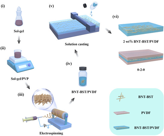
Figure 1. Schematic of the fabrication process for 0.55Bi0.5Na0.5TiO3-0.45(Sr0.7Bi0.2)TiO3 (BNT-BST)/ polyvinylidene difluoride (PVDF) nanocomposites. (i) Configuring the sol-gel of BNT-BST. (ii) Mixing of polyvinylpyrrolidone and BNT-BST sol-gel. (iii) Electrospinning process. (iv) Dispersion process of BNT-BST nanofibers in PVDF. (v) Solution-casting process. (vi) Schematic of nanocomposites.
Characterization. X-ray diffraction (Advance D8), scanning electron microscopy (MIRA4 LMH), piezoelectric force microscopy (Nanoman TM VS), thermogravimetric analysis (TGA, 8000-FTIR-GCMS), transmission electron microscopy (TEM, Titan G2 60-300), and X-ray photoelectron spectroscopy (XPS, ESCALAB250Xi) were employed to investigate the microstructural information of BNT-BST nanofibers. The dielectric properties, displacement hysteresis loops, and pulse discharge performance of nanocomposites were characterized using an Agilent 4990A, TF Analyzer 2000 (aixACT, Germany) at
RESULTS AND DISCUSSION
The crystallinity of BNT-BST nanofibers is shown in Figure 2A. Refinement of the raw X-ray diffraction data revealed that BNT-BST had a two-phase coexistence with 90.012% of the P4bm (PDF#70-4760) phase and 9.988% of the R3c (PDF#36-0153) phase, respectively. Figure 2B shows the microscopic topography of the electrospun precursors that have nanofibers before sintering. The diameter of the nanofibers obtained from the electrospinning precursors was ~260-650 nm, with an average diameter of 498.8 nm. The precursor nanofibers had a smooth exterior. To further determine the sintering parameters of electrospun nanofibers, the precursor nanofibers were subjected to TGA; the result is shown in Figure 2C. The weight losses were 10.82% (30-180 °C), 38.67% (180-400 °C), and 12.11% (400-800 °C) due to the rapid vaporization of the electrospinning solution, breakdown of the acetate ligand, and pyrolysis of the gel, respectively[30,31]. According to TGA, BNT-BST nanofibers can be produced by maintaining the electrospun nanofibers at
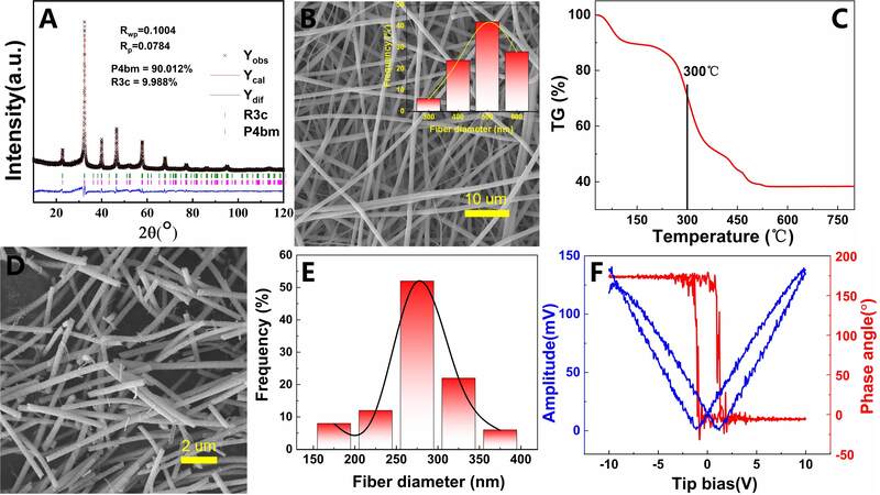
Figure 2. (A) X-ray diffraction pattern of 0.55Bi0.5Na0.5TiO3-0.45(Sr0.7Bi0.2)TiO3 (BNT-BST) nanofibers. (B) Scanning electron microscopy (SEM) image before sintering. (C) Thermogravimetric analysis of electrospinning nanofibers. (D) SEM image after sintering. (E) Diameter distribution. (F) Piezoelectric force microscopy image of BNT-BST nanofibers.
The structure of the BNT-BST nanofibers was determined via TEM. Figure 3A is a TEM image of a BNT-BST nanofiber. Figure 3B demonstrates that the localized region has a lattice spacing of 0.295 nm, which corresponds to the (110) plane of the BNT-BST nanofiber. Figure 3B demonstrates the presence of distinct lattice fringes in a second region with an interplanar space of 0.390 nm, which is generated by the (101) plane of the BNT-BST nanofibers. The insets of Figure 3B and C show the selected area electron diffraction patterns along the [111] and [110] orientations for the corresponding selected areas, respectively. These results are comparable to those described in the literature, demonstrating further that BNT-BST nanofibers exhibit a pseudocubic phase with polar nano regions[22,32]. Figure 3D shows the element mapping images for O, Na, Ti, Sr, and Bi elements. O, Na, Ti, Sr, and Bi elements appear to be consistently distributed in BNT-BST nanofiber.

Figure 3. (A) Transmission electron microscopy (TEM) image. (B and C) High-resolution TEM images. (D) Element mapping images of 0.55Bi0.5Na0.5TiO3-0.45(Sr0.7Bi0.2)TiO3 nanofiber.
Figure 4A shows the XPS survey spectrum of BNT-BST nanofibers, in which the presence of Bi 4f, Na 1s,
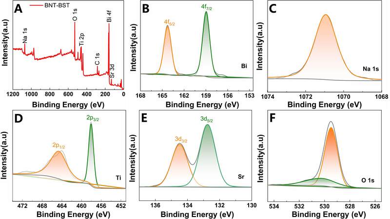
Figure 4. X-ray photoelectron spectroscopy spectra of 0.55Bi0.5Na0.5TiO3-0.45(Sr0.7Bi0.2)TiO3 nanofibers: (A) survey spectra, (B) Bi,
Figure 5 depicts dielectric properties as a function of frequency for monolayer and trilayer BNT-BST/PVDF nanocomposites. The dielectric constant (ε) of the monolayer BNT-BST/PVDF nanocomposite decreased steadily with frequency owing to the intrinsic dielectric relaxation of the PVDF polymer[29,33]. For instance, the ε of monolayer BNT-BST/PVDF nanocomposites with 8 wt% BNT-BST nanofibers was 12.12 at 103 Hz and 7.28 at 107 Hz [Figure 5A]. Figure 5A and B demonstrate that the incorporation of BNT-BST nanofibers may increase the dielectric constant of PVDF-based nanocomposites. At 1 kHz, the ε of pure PVDF, 1 wt%, 2 wt%, 4 wt%, 6 wt%, and 8 wt% monolayer BNT-BST/PVDF nanocomposites, respectively, were 9.53, 10.29, 10.49, 10.86, 11.57, and 12.12. The ε was increased owing to the intrinsically high dipole polarization of BNT-BST nanofibers and the interfacial polarization in the nanocomposites. The interface between the BNT-BST/PVDF layer and the pure PVDF layer must be considered in nanocomposites with a trilayer structure. The electron trap would form at the interface and gather at the region of interface, thus enhancing interfacial polarization and increasing permittivity[36]. Figure 5C shows the frequency-dependent dielectric loss of monolayer BNT-BST/PVDF nanocomposites. The dielectric loss of nanocomposites is primarily caused by two factors: conduction loss and polarization loss[37].
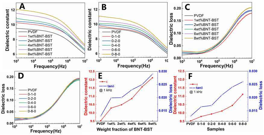
Figure 5. (A and B) ε and (C and D) dielectric loss of monolayer and trilayer nanocomposites. (E and F) ε and dielectric loss at 1 kHz of nanocomposites with various 0.55Bi0.5Na0.5TiO3-0.45(Sr0.7Bi0.2)TiO3 nanofiber loadings.
As shown in Figure 5B and D, the frequency dependence of the dielectric characteristics of the symmetric trilayer nanocomposites is comparable to that of the monolayer BNT-BST/PVDF nanocomposites. The analysis of ε and dielectric loss at 1 kHz of the nanocomposites is shown in Figure 5E and F. Notably, the most significant enhancement was observed at 8 wt% monolayer BNT-BST/PVDF nanocomposites, i.e., from 9.53 for pure PVDF to 12.12 at 1 kHz, which is a 27% improvement. It is important to note that the dielectric loss of monolayer BNT-BST/PVDF nanocomposites was consistently larger than that of trilayer nanocomposites at the same mass fractions. The dielectric loss of 1 wt%, 2 wt%, 4 wt%, 6 wt%, and 8 wt% monolayer BNT-BST/PVDF nanocomposites was 0.0199, 0.0201, 0.0228, 0.0253, and 0.0288, respectively, as shown in Figure 5E. Figure 5F shows the dielectric loss at 1 kHz for 0-1-0, 0-2-0, 0-4-0, 0-6-0, and 0-8-0 trilayer BNT-BST nanocomposites to be 0.0165, 0.0172, 0.0206, 0.0243, and 0.0261, respectively. This is primarily attributable to the trilayer structure. Compared to the BNT-BST/PVDF nanocomposite layer, the pure PVDF outer layer in the symmetric trilayer nanocomposites had lower electron mobility and greater insulation, as well as limited charge injection at the dielectric/dielectric interface. In addition, a high number of deep traps existed at the interlayer interface of the trilayer structure, thereby impeding the long-distance migration of electrons and reducing the leakage current considerably[15,29,38].
Figure 6A and B show the corresponding P-E loops for each nanocomposite at the maximum breakdown electric field. The BNT-BST nanofibers can enhance saturation polarization at high electric fields due to the wide enclosed area between the P-E loop and the vertical P axis, which is advantageous for attaining a larger discharge energy density in the nanocomposite. In addition to high saturation polarization, achieving high breakdown strength (Eb) is crucial for obtaining a high discharge energy density. The effect of BNT-BST nanofibers with a high aspect ratio on the breakdown strength of nanocomposites is effectively illustrated here using the Weibull statistical Equation (1):

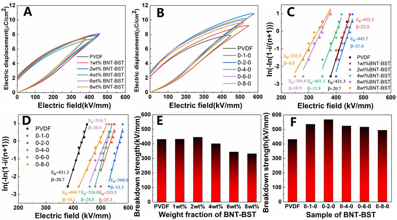
Figure 6. (A and B) P-E loops. (C and D) Weibull plots. (E and F) Eb from Weibull plots of monolayer and trilayer nanocomposites.
where P(E), E, Eb, and β are the cumulative failure probability, breakdown electric field of the experimental test sample, breakdown strength with a nanocomposite breakdown probability of 63.2%, and shape parameter or slope obtained by fitting, respectively. As shown in Figure 6C and D, the breakdown electric field was measured at least nine times for each nanocomposite, and the results were calculated using Weibull statistics. The Weibull distribution breakdown electric field for each nanocomposite sample is displayed in Figure 6E and F. For example, the Eb of pure PVDF, 1 wt%, 2 wt%, 4 wt%, 6 wt%, and 8 wt% monolayer BNT-BST/PVDF nanocomposites was 431.3 kV/mm, 432.5 kV/mm, 445.7 kV/mm,
Figure 7 shows the variation curves of discharge energy density (Udis) and energy efficiency (η) for each sample with varying electric fields as determined by the integration of P-E loops. Figure 7A and B show that the Udis value of the same sample increases monotonically with the applied electric field. In the same electric field, the introduction of BNT-BST nanofibers and interfacial polarization results in an increase in electrical displacement with increasing BNT-BST nanofiber loading. The electric field is high, as is the integral value of the effective area, and Udis are large. However, Figure 7C and D show that η first decreases and then increases with an electric field, which is mostly attributable to the ferroelectric conversion in PVDF[41]. Under the same electric field, η first increases and then decreases with the increased loading of BNT-BST nanofibers. As the outermost layer, pure PVDF can sustain a greater external electric field, mitigating the effect of electric field concentration within the nanocomposite. The interface between BNT-BST nanofibers and pure PVDF matrix, as well as the interlayer interface of the trilayer structure, inhibited the extension and growth of the electrical tree and reduced the increase in leakage current, both of which are advantageous for preventing early dielectric breakdown and promoting the improvement of Eb and η. Therefore, the synergy between the outer insulating layer and the central composite layer is key to concurrently improving Udis and η[27,28]. However, the overloaded BNT-BST nanofibers lead to an increase in defects and leakage current, which reduces Udis and η. Figure 7E and F show the corresponding Udis and η for each sample at the maximum breakdown electric field. For example, the Udis and η of pure PVDF and symmetric trilayer nanocomposites were 9.12 J/cm3 (45.72%), 14.05 J/cm3 (51.63%), 17.37 J/cm3 (52.93%), 14.43 J/cm3 (49.34%), 13.61 J/cm3 (49.34%), and 13.01 J/cm3 (48.98%), respectively. Figure 7F reveals that the Udis and η of the 0-2-0 sample are 17.37 J/cm3 and 52.93%, respectively, at 580 kV/mm, which are 90.5% and 7.2% more than those of pure PVDF (9.12 J/cm3 and 45.72% at 450 kV/mm).
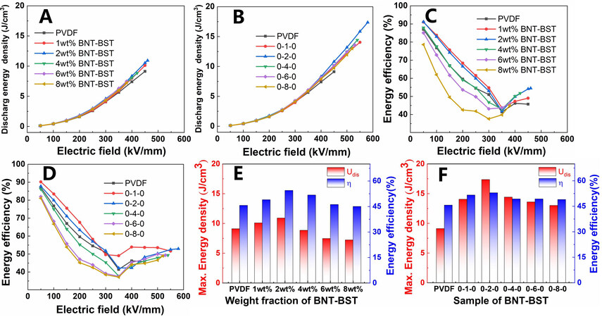
Figure 7. (A and B) Udis, (C and D) η, (E and F) Udis and η at each EMax of monolayer and trilayer nanocomposites.
To better characterize the uniform stability of the 0-2-0 sample, the average values of Udis and η of the 0-2-0 sample in several places with varying electric fields were measured, as shown in Figure 8A and B. The variation patterns of Udis and η for the electric field were consistent, as shown in Figure 7. In addition, the radar chart emphasized the overall performance of the 0-2-0 sample. The larger the area of the radar chart, the better the overall performance of the nanocomposites. The five parameters of Udis, η, β, ε, and Eb of pure PVDF, 2 wt% monolayer BNT-BST/PVDF nanocomposites, and the symmetric trilayer 0-2-0 sample are compared in Figure 8C. The results show that the area encompassed by the 0-2-0 sample is the largest, indicating that the 0-2-0 sample has superior performance in all respects. Finally, the overdamped discharge curve of the 0-2-0 sample in various electric fields was examined using a dielectric material charge measurement system with a resistance of 10 kΩ [Figure 8D and E]. The peak current reached 0.505 A for 0.228 μs. Figure 8F shows that the pulse discharge energy density (Wd) of the 0-2-0 sample is 5.30 J/cm3 at 400 kV/mm and 10 μs compared with 3.10 J/cm3 for pure PVDF.
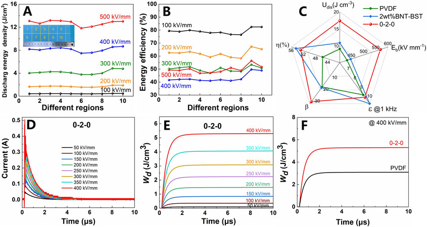
Figure 8. (A) Udis and (B) η of different regions of the 0-2-0 sample tested with different electric fields. (C) Radar plots of pure polyvinylidene difluoride (PVDF), 2 wt% monolayer 0.55Bi0.5Na0.5TiO3-0.45(Sr0.7Bi0.2)TiO3 (BNT-BST)/PVDF and trilayer 0-2-0 sample. (D) Overdamped discharge curves. (E) Time dependence of Wd with different electric fields of the 0-2-0 sample. (F) Variation rule of Wd with time for pure PVDF and the 0-2-0 sample at 400 kV/mm.
CONCLUSIONS
In conclusion, BNT-BST nanofibers with high aspect ratios were prepared using the electrospinning method. Monolayer and symmetric trilayer PVDF-based nanocomposites with varied BNT-BST nanofiber loadings were prepared using the solution-casting method. It was proved that trilayer nanocomposites are more effective than monolayer nanocomposites at enhancing the energy storage performance of dielectric nanocomposites. The reason is that a pure PVDF layer with excellent insulating properties helps prevent charge injection and current leakage by inhibiting the development of electrical trees. Therefore, a high energy density of 17.37 J/cm3 and an efficiency of 52.93% are simultaneously achieved in the optimized 0-2-0 sample. We believe that the trilayer design strategy is crucial for investigating dielectric capacitors with high energy density.
DECLARATIONS
Authors’ contributionsConception, design, writing and editing: Liu Y, Luo H, Zhang D
Materials synthesis and structural characterizations: Liu Y, Zhou X, Jiang X
Data analysis and interpretation: Liu Y, Xie H, Xiao Z, Wang F
All authors contributed to the manuscript and were involved in discussion.
Availability of data and materialsNot applicable.
Financial support and sponsorshipThe authors acknowledge the support of National Natural Science Foundation of China (52172265 and 52002404), Scientific research project of Hunan Provincial Department of Education (21B0009), Hunan Excellent Youth Science Foundation (2022JJ20067), The science and technology innovation Program of Hunan Province(2022RC1074), Central South University Innovation-Driven Research Program (2023CXQD010) and State Key Laboratory of Powder Metallurgy, Central South University, Changsha, China.
Conflicts of interestAll authors declared that there are no conflicts of interest.
Ethical approval and consent to participateNot applicable.
Consent for publicationNot applicable.
Copyright© The Author(s) 2023.
REFERENCES
1. Ren X, Meng N, Ventura L, et al. Ultra-high energy density integrated polymer dielectric capacitors. J Mater Chem A 2022;10:10171-80.
2. Feng QK, Zhong SL, Pei JY, et al. Recent progress and future prospects on all-organic polymer dielectrics for energy storage capacitors. Chem Rev 2022;122:3820-78.
3. Liu S, Kang L, Hu J, et al. Realizing superior redox kinetics of hollow bimetallic sulfide nanoarchitectures by defect-induced manipulation toward flexible solid-state supercapacitors. Small 2022;18:e2104507.
4. Kang L, Zhang M, Zhang J, et al. Dual-defect surface engineering of bimetallic sulfide nanotubes towards flexible asymmetric solid-state supercapacitors. J Mater Chem A 2020;8:24053-64.
5. Yang L, Kong X, Li F, et al. Perovskite lead-free dielectrics for energy storage applications. Prog Mater Sci 2019;102:72-108.
6. Luo H, Wang F, Guo R, et al. Progress on polymer dielectrics for electrostatic capacitors application. Adv Sci 2022;9:e2202438.
7. Thakur VK, Gupta RK. Recent progress on ferroelectric polymer-based nanocomposites for high energy density capacitors: synthesis, dielectric properties, and future aspects. Chem Rev 2016;116:4260-317.
8. Li H, Ai D, Ren L, et al. Scalable polymer nanocomposites with record high-temperature capacitive performance enabled by rationally designed nanostructured inorganic fillers. Adv Mater 2019;31:e1900875.
9. Zhou Y, Luo H, Chen S, Han X, Zhang D. Optimising the dielectric property of carbon nanotubes/P(VDF-CTFE) nanocomposites by tailoring the shell thickness of liquid crystalline polymer modified layer. IET Nanodielectr 2019;2:142-50.
10. Cheng R, Wang Y, Men R, et al. High-energy-density polymer dielectrics via compositional and structural tailoring for electrical energy storage. iScience 2022;25:104837.
11. Dong J, Hu R, Niu Y, et al. Enhancing high-temperature capacitor performance of polymer nanocomposites by adjusting the energy level structure in the micro-/meso-scopic interface region. Nano Energy 2022;99:107314.
12. Luo H, Zhou X, Ellingford C, et al. Interface design for high energy density polymer nanocomposites. Chem Soc Rev 2019;48:4424-65.
13. Li L, Cheng J, Cheng Y, et al. Significant improvements in dielectric constant and energy density of ferroelectric polymer nanocomposites enabled by ultralow contents of nanofillers. Adv Mater 2021;33:e2102392.
14. Cheng Y, Pan Z, Bai H, et al. Two-dimensional fillers induced superior electrostatic energy storage performance in trilayered architecture nanocomposites. ACS Appl Mater Interfaces 2022;14:8448-57.
15. Liu Y, Luo H, Zhai D, et al. Symmetric trilayer dielectric composites with high energy density using a low loading of KNbO3 nanosheets. ACS Sustain Chem Eng 2021;9:15983-94.
16. Zhang H, Marwat MA, Xie B, et al. Polymer matrix nanocomposites with 1D ceramic nanofillers for energy storage capacitor applications. ACS Appl Mater Interfaces 2020;12:1-37.
17. Pan Z, Yao L, Zhai J, Yang K, Shen B, Wang H. Ultrafast discharge and high-energy-density of polymer nanocomposites achieved via optimizing the structure design of barium titanates. ACS Sustain Chem Eng 2017;5:4707-17.
18. Song Y, Shen Y, Liu H, Lin Y, Li M, Nan C. Improving the dielectric constants and breakdown strength of polymer composites: effects of the shape of the BaTiO3 nanoinclusions, surface modification and polymermatrix. J Mater Chem 2012;22:16491.
19. Zhou X, Xue G, Luo H, Bowen CR, Zhang D. Phase structure and properties of sodium bismuth titanate lead-free piezoelectric ceramics. Prog Mater Sci 2021;122:100836.
20. Shen Y, Wu L, Zhao J, et al. Constructing novel binary Bi0.5Na0.5TiO3-based composite ceramics for excellent energy storage performances via defect engineering. Chem Eng J 2022;439:135762.
21. Ma Y, Xie H, Sun Y, et al. Topochemical synthesis and structural characteristics of orientation-controlled (Bi0.5Na0.5)0.94Ba0.06TiO3 perovskite microplatelets. Microstructures 2022;2:2022006.
22. Li J, Li F, Xu Z, Zhang S. Multilayer lead-free ceramic capacitors with ultrahigh energy density and efficiency. Adv Mater 2018;30:e1802155.
23. You D, Tan H, Yan Z, et al. Enhanced dielectric energy storage performance of 0.45Na0.5Bi0.5TiO3-0.55Sr0.7Bi0.2TiO3/AlN 0-3 type lead-free composite ceramics. ACS Appl Mater Interfaces 2022;14:17652-61.
24. Ang C, Yu Z. High remnant polarization in Sr0.7Bi0.2TiO3-Na0.5Bi0.5TiO3 solid solutions. Appl Phys Lett 2009;95:232908.
25. Xue J, Wu T, Dai Y, Xia Y. Electrospinning and electrospun nanofibers: methods, materials, and applications. Chem Rev 2019;119:5298-415.
26. Chen J, Zhang X, Wang Z, Chen W, Yuan Q, Wang Y. Laminated ferroelectric polymer composites exhibit synchronous ultrahigh discharge efficiency and energy density via utilizing multiple-interface barriers. J Mater Chem A 2022;10:20402-13.
27. Feng M, Feng Y, Zhang T, et al. Recent advances in multilayer-structure dielectrics for energy storage application. Adv Sci 2021;8:e2102221.
28. Wang Y, Yao M, Ma R, et al. Design strategy of barium titanate/polyvinylidene fluoride-based nanocomposite films for high energy storage. J Mater Chem A 2020;8:884-917.
29. Guo R, Luo H, Yan M, Zhou X, Zhou K, Zhang D. Significantly enhanced breakdown strength and energy density in sandwich-structured nanocomposites with low-level BaTiO3 nanowires. Nano Energy 2021;79:105412.
30. Zhang Y, Jeong CK, Yang T, et al. Bioinspired elastic piezoelectric composites for high-performance mechanical energy harvesting. J Mater Chem A 2018;6:14546-52.
31. Liu Y, Luo H, Gao Z, et al. Electrospinning synthesis of Na0.5Bi0.5TiO3 nanofibers for dielectric capacitors in energy storage application. Nanomaterials 2022;12:906.
32. Li J, Shen Z, Chen X, et al. Grain-orientation-engineered multilayer ceramic capacitors for energy storage applications. Nat Mater 2020;19:999-1005.
33. Liu Y, Luo H, Zhai D, et al. Improved energy density and energy efficiency of poly(vinylidene difluoride) nanocomposite dielectrics using 0.93Na0.5Bi0.5TiO3-0.07BaTiO3 nanofibers. ACS Appl Mater Interfaces 2022;14:19376-87.
34. Ma Y, Luo H, Zhou X, et al. Suppressed polarization by epitaxial growth of SrTiO3 on BaTiO3 nanoparticles for high discharged energy density and efficiency nanocomposites. Nanoscale 2020;12:8230-6.
35. Zhou X, Sun Q, Zhai D, Xue G, Luo H, Zhang D. Excellent catalytic performance of molten-salt-synthesized Bi0.5Na0.5TiO3 nanorods by the piezo-phototronic coupling effect. Nano Energy 2021;84:105936.
36. Wang Y, Cui J, Yuan Q, Niu Y, Bai Y, Wang H. Significantly enhanced breakdown strength and energy density in sandwich-structured barium titanate/poly(vinylidene fluoride) nanocomposites. Adv Mater 2015;27:6658-63.
37. Pei JY, Yin LJ, Zhong SL, Dang ZM. Suppressing the loss of polymer-based dielectrics for high power energy storage. Adv Mater 2022:e2203623.
38. Jiang J, Shen Z, Qian J, et al. Synergy of micro-/mesoscopic interfaces in multilayered polymer nanocomposites induces ultrahigh energy density for capacitive energy storage. Nano Energy 2019;62:220-9.
39. Lin Y, Zhang Y, Zhan S, et al. Synergistically ultrahigh energy storage density and efficiency in designed sandwich-structured poly(vinylidene fluoride)-based flexible composite films induced by doping Na0.5Bi0.5TiO3 whiskers. J Mater Chem A 2020;8:23427-35.
40. Wang Z, Feng Z, Tang H, et al. Effects of Nanofibers orientation and aspect ratio on dielectric properties of nanocomposites: a phase-field simulation. ACS Appl Mater Interfaces 2022;14:42513-21.
Cite This Article
Export citation file: BibTeX | RIS
OAE Style
Liu Y, Luo H, Xie H, Xiao Z, Wang F, Jiang X, Zhou X, Zhang D. Trilayer PVDF nanocomposites with significantly enhanced energy density and energy efficiency using 0.55Bi0.5Na0.5TiO3-0.45(Sr0.7Bi0.2)TiO3 nanofibers. Microstructures 2023;3:2023008. http://dx.doi.org/10.20517/microstructures.2022.31
AMA Style
Liu Y, Luo H, Xie H, Xiao Z, Wang F, Jiang X, Zhou X, Zhang D. Trilayer PVDF nanocomposites with significantly enhanced energy density and energy efficiency using 0.55Bi0.5Na0.5TiO3-0.45(Sr0.7Bi0.2)TiO3 nanofibers. Microstructures. 2023; 3(1): 2023008. http://dx.doi.org/10.20517/microstructures.2022.31
Chicago/Turabian Style
Liu, Yuan, Hang Luo, Haoran Xie, Zhida Xiao, Fan Wang, Xun Jiang, Xuefan Zhou, Dou Zhang. 2023. "Trilayer PVDF nanocomposites with significantly enhanced energy density and energy efficiency using 0.55Bi0.5Na0.5TiO3-0.45(Sr0.7Bi0.2)TiO3 nanofibers" Microstructures. 3, no.1: 2023008. http://dx.doi.org/10.20517/microstructures.2022.31
ACS Style
Liu, Y.; Luo H.; Xie H.; Xiao Z.; Wang F.; Jiang X.; Zhou X.; Zhang D. Trilayer PVDF nanocomposites with significantly enhanced energy density and energy efficiency using 0.55Bi0.5Na0.5TiO3-0.45(Sr0.7Bi0.2)TiO3 nanofibers. Microstructures. 2023, 3, 2023008. http://dx.doi.org/10.20517/microstructures.2022.31
About This Article
Special Issue
Copyright

Data & Comments
Data
0

 Cite This Article 14 clicks

 Like This Article 0
likes
Like This Article 0
likes


Comments
Comments must be written in English. Spam, offensive content, impersonation, and private information will not be permitted. If any comment is reported and identified as inappropriate content by OAE staff, the comment will be removed without notice. If you have any queries or need any help, please contact us at support@oaepublish.com.